The purpose of this article is to explain how to incorporate some of the built-in Processing functionality that is generally underutilized. Processing has a wealth of features that allow you to achieve high quality results without needing to learn linear algebra and write custom shaders.
Spatial anti-aliasing is easiest way to improve the visual quality of your sketch. When images are rendered at a higher resolution and down-sampled, the edges of polygons appear softer.
          void setup(){
            size(1024,768);
            smooth(8);
          }
          void draw(){}
The function in processing that facilitates anti-aliasing is smooth(). Smooth accepts, as an argument, the factor of anti-aliasing. smooth(2) is the default setting, which means that your scene is rendered twice as large as you specify in your size() function, and displayed on the screen in the dimensions you specify. Calling smooth(4) after your code>size() function should (at least slightly) improve the quality of the geometry of your sketch. You can call noSmooth() after your size() function to see how awful your sketch could look without any anti-aliasing. If you are going for an 8-bit graphics look, be sure to call noSmooth() to get that retro "jaggies" effect.
For most graphics cards smooth() accepts an argument value up to 8. High performance discrete GPUs can have hardware acceleration for anti-aliasing and can go as high as 32x. Professional (non-consumer grade) graphics cards can support up to 64x anti-aliasing. In the Processing examples under Demos > Tests, there is a sketch called 'SmoothTest' that will help you determine the maximum level of anti-aliasing your graphics card supports.
For simple scenes with large shapes there are diminishing returns for higher anti-aliasing multipliers. There are also memory and rendering speed considerations at play when performing anti-aliasing. The larger your anti-aliasing factor, the slower your sketch will run.
          void setup(){
            size(800,800,P3D);
            smooth(8);
          }
          void draw(){
            background(0);

            lights(); // !!!!

            fill(33,66,255);

            noStroke();
            pushMatrix();
              translate(width * 0.5, height * 0.5);
              rotateX(-PI * 0.2);
              rotateY(PI * 0.3);
              box(width * 0.33);
            popMatrix();
          }
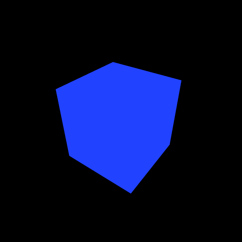
When calling the size function you specify width and height, but you can also specify a renderer. For Processing this means specifying the default shader used to render your scene. Selecting the P3D renderer exposes a lot of advanced functionality that can improve the visual quality of your sketch.
If you specify the P3D renderer in your size() function, and call lights() during your draw function, your sketch will immediately reap the benefits of a per-pixel rendering technique called phong shading. Calling lights() in your draw function will create a grey ambient light, and a grey directional light coming from the viewers perspective pointed into the depth (z-axis) of the scene. The difference is striking. Cubes and spheres will actually appear to be 3-dimensional.
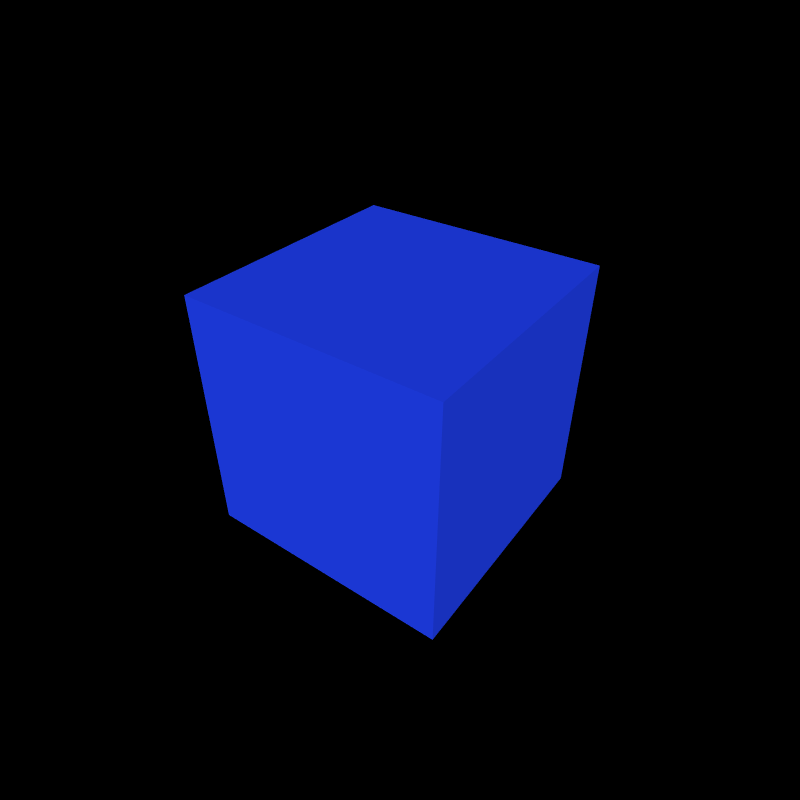
As the objects in the scene move their position and rotate relative to the light sources, the surfaces will (somewhat) accurately reproduce natural lighting conditions. Surfaces facing the light sources will appear brighter by reflecting more of the light than surfaces pointed away from the light source. That behavior is the foundation of almost all real-time rendering algorithms, and is used to great effect when combined with up to eight instances of four different styles of lights.
          void setup(){
            size(800,800,P3D);
            smooth(8);
          }
          void draw(){
            background(0);

            ambientLight(128,128,128);

            noStroke();
            pushMatrix();
              translate(width * 0.5, height * 0.5);
              rotateX(-PI * 0.2);
              rotateY(PI * 0.3);

              // fill(255,0,0); // Stop using fill().
              ambient(255,0,0); // material setting
              box(width * 0.33);
            popMatrix();
          }
You could have just as easily stopped at calling the lights() function and considered the improvement a job well done. If you want to dig deeper you can get more interesting effects.
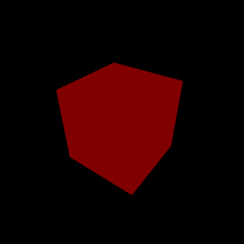
The simplest type of light applied to a scene is the ambient light. It illuminates all polygons in the scene the same way regardless of their position and orientation. You specify the color of your polygons by using the ambient() function. When calling ambient() you are specifying the way the polygons drawn afterwards will respond to the ambientLight(). ambient() works just like fill() in that it accepts a red, green, and blue value, but it will not accept an alpha channel value.
If the color in your ambientLight() overlaps with the ambient() material, the object will be illuminated with the color of the overlap.
          void setup(){
            size(800,800,P3D);
            smooth(8);
          }
          void draw(){
            background(0);

            ambientLight(0,128,128);

            noStroke();
            pushMatrix();
              translate(width * 0.5, height * 0.5);
              rotateX(-PI * 0.2);
              rotateY(PI * 0.3);

              // fill(255,0,0); // =(
              ambient(255,255,0);
              box(width * 0.33);
            popMatrix();
          }
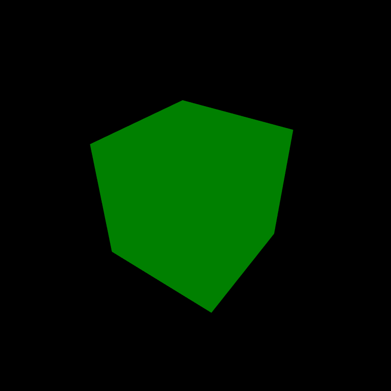
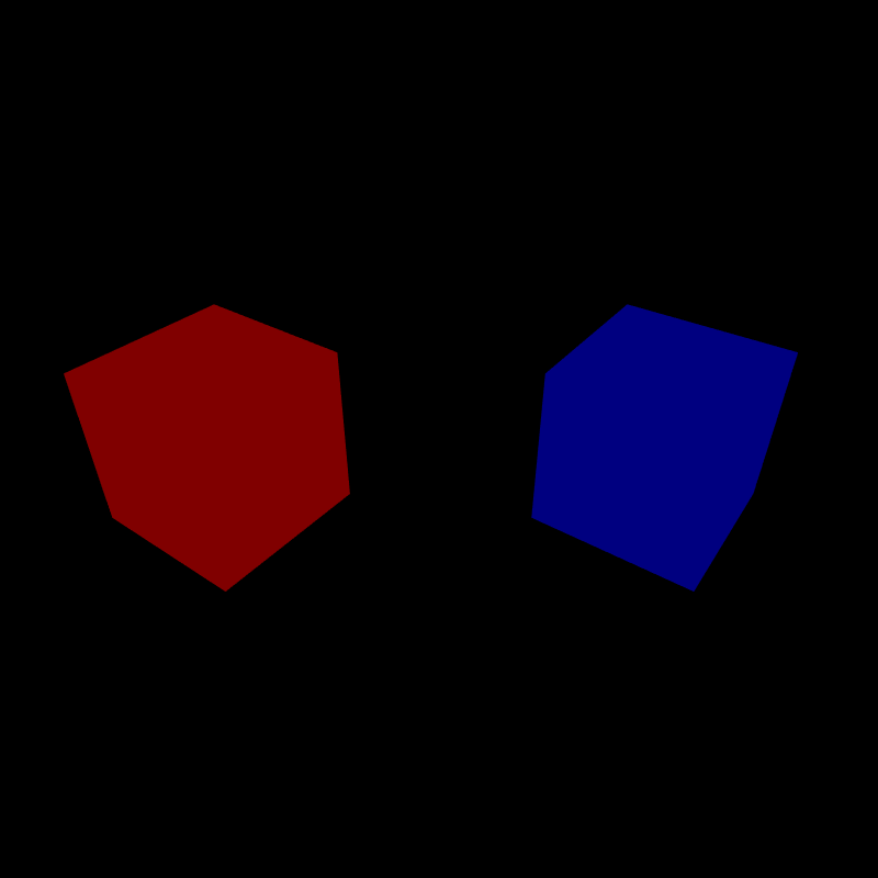
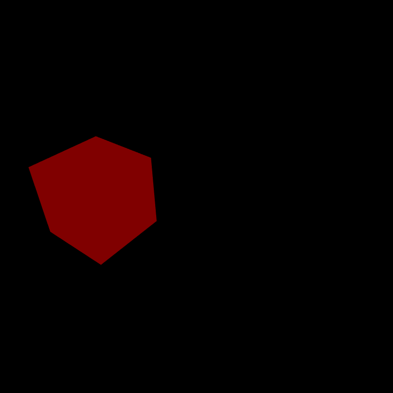
ambient(), the box appears green because there was no red present in the ambientLight(). If a grey value was passed (ex.
ambientLight(128,128,128)) the box would have been yellow.If you call ambientLight(128,0,0), only objects whose ambient material is active in the red channel would reflect the light. A blue cube has no red component, so it does not reflect any red light. A red ambient light rendered the blue cube black.
Earlier when we called the lights() function in our sketch. Two lights were automatically added to the sketch. A grey ambient light ambientLight(128,128,128) was added, along with a directional light.
A directional light accepts red, green, and blue values just like the ambient light, but it also accepts arguments that describe the direction the light is pointing described as a 3 component vector. You do not specify a position when creating a directionaLight() because it is positioned 'infinitely' far away. Think of a directional light as if it were the sun in the sky.
          void setup(){
            size(800,800,P3D);
            smooth(8);
          }
          void draw(){

            background(0);

            ambientLight(64,64,64);

            if(mousePressed){
              directionalLight(128,128,128, 0, 0, -1);  // light from viewer
            } else {
              directionalLight(128,128,128, 0, 1, 0);   // light from above
            }

            noStroke();
            pushMatrix();
              translate(width * 0.5, height * 0.5, -width * 0.25);

              ambient(33,66,255);
              sphere(width * 0.25);
            popMatrix();
          }
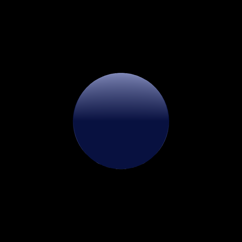
(positive y direction component)
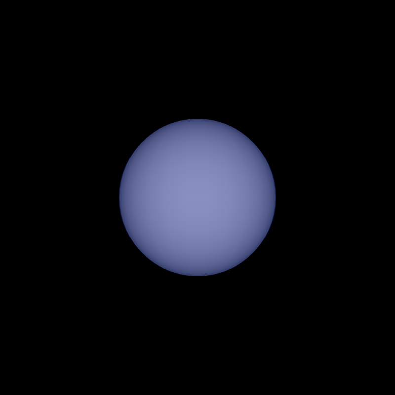
(negative z direction component)
Adding a directionalLight() to the sketch has given a sense of depth to the polygons drawn to the screen. This is because the directional light works differently than the ambient light. The polygons that are facing the source of the directional light are brighter than the polygons facing away from the source. This effect is called diffuse reflection.
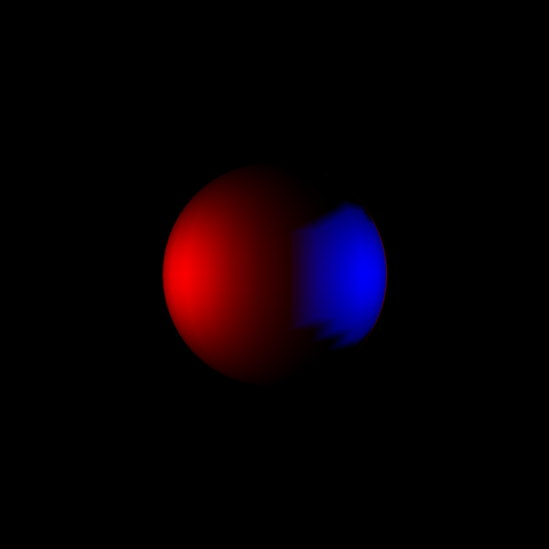
A spotlight is a type of directional light that is not coming from infinitely far away. That is to say, it has a source position. It also accepts as arguments, an angle describing the width of the cone of the light, and a value for the concentration of the brightness of the light within that cone.
          void setup(){
            size(800,800,P3D);
            smooth(8);
          }

          void draw(){

            noStroke();
            background(0);

            spotLight(255, 0, 0, 0, height/2, 400, 1, 0, -1, PI, 32);
            spotLight(0, 0, 255, width, height/2, 400, -1, 0, -1, PI/16.0, 32);

            pushMatrix();
              translate(width * 0.5, height * 0.5, 0);
              sphere(width * 0.2);
            popMatrix();
          }
          void setup(){
            size(800,800,P3D);
            smooth(8);

          }
          void draw(){
            noStroke();
            background(0);

            spotLight(33, 66, 255, width * 0.5, height * 0.1,
                      0, cos(frameCount * 0.05), 1, 0,
                      PI, 100);

            for(int i = 0; i < 5; i++){
              float xTranslate = map(i, 0, 4, width * 0.1, width * 0.9);
              pushMatrix();
                translate(xTranslate, height * 0.5, 0);

                sphere(width * 0.05);
              popMatrix();

            }
          }
A point light is commonly described as a spotlight that does not require a direction vector. It emits light in all directions.
          void setup(){
            size(800,800,P3D);
            smooth(8);
          }
          void draw(){
            background(0);

            pointLight(255, 0, 0, mouseX, mouseY, 64);
            pointLight(0, 0, 255, width - mouseX, height - mouseY, 64);

            noStroke();
            pushMatrix();
              translate(width * 0.5, height * 0.5, -width * 0.25);
              sphere(width * 0.25);
            popMatrix();
          }
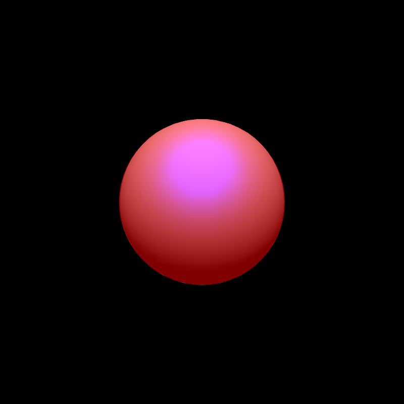
So far we have seen our polygons react to light in a single way. Objects have a color, and when a light that contains some amount of that color shines on it, the overlapping color components are reflected. That works fine for most things.
If your sketch contains a red rubber ball, and a white light shines on it, a diffuse red light is reflected in all directions. If that ball were to land in a puddle, it would react to light differently. The water on the surface of the ball would shine, or reflect a specular light, more commonly referred to as a highlight. The P3D renderer can simulate this effect by specifying additional light properties and material properties.
          void setup(){
            size(800,800,P3D);
            smooth(8);
            noStroke();
          }
          void draw(){
            background(0);

            ambientLight(128, 128, 128);

            lightSpecular(128,128,128);
            directionalLight(128,128,128, cos(frameCount * 0.1), 1, -1);

            pushMatrix();
              translate(width * 0.25, height * 0.5, 0);

              specular(0,0,0);      // the equivalent of no specular light
              ambient(255,0,0);
              sphere(width * 0.2);

            popMatrix();

            pushMatrix();
              translate(width * 0.75, height * 0.5, 0);

              specular(255,255,255);
              ambient(255,0,0);
              sphere(width * 0.2);

            popMatrix();
          }
Two new things are happening here. First is the call to lightSpecular() that specifies the specular light for the directional light added to the scene immediately afterwards. You also specify the color of the specular highlight along with the ambient / diffuse color.
The specular component of a material can also be altered to take into account how 'shiny' the material is. The shinier the material, the more focused the specular highlight is.
          void setup(){
            size(800,800,P3D);
            smooth(8);
            noStroke();
          }
          void draw(){
            background(0);

            ambientLight(128, 128, 128);

            lightSpecular(128,128,128);
            directionalLight(128,128,128, 0, 1, -1);

            pushMatrix();
              translate(width * 0.5, height * 0.5, 0);

              specular(255,255,255);
              shininess(1.0 + (100 * abs(cos(frameCount * 0.1))));
              ambient(255,0,0);
              sphere(width * 0.2);

            popMatrix();
          }
The specular component of the material can be entirely different from the ambient component of the material.
          void setup(){
            size(800,800,P3D);
            smooth(8);
            noStroke();
          }
          void draw(){
            background(0);

            ambientLight(128, 128, 128);

            lightSpecular(255,255,255);
            directionalLight(128,128,128, 0, 1, -1);

            pushMatrix();
              translate(width * 0.5, height * 0.5, 0);

              specular(0,0,255);
              shininess(10.0);
              ambient(255,0,0);
              sphere(width * 0.2);

            popMatrix();
          }
The third material property specified in the Processing documentation is the emissive property. This is a misnomer in the sense that the material does not actually emit light that effects surrounding polygons. Instead, it gives the appearance that the object is glowing.
          void setup(){
            size(800,800,P3D);
            smooth(8);
            noStroke();
          }
          void draw(){

            background(0);

            ambientLight(128, 128, 128);

            pushMatrix();
              translate(width * 0.25, height * 0.5, 0);

              ambient(0,0,0);
              emissive(255,0,0);
              sphere(width * 0.2);

            popMatrix();

            pushMatrix();
              translate(width * 0.75, height * 0.5, 0);

              ambient(255,0,0);
              emissive(0,0,0);
              sphere(width * 0.2);

            popMatrix();
          }
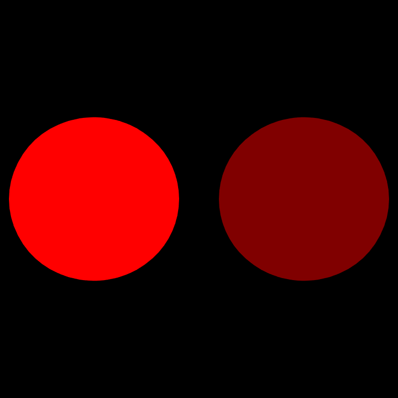
Emissive lights are effectively an ambient material that is at full strength under any level of ambient light, even if the ambient light is not emitting light in an overlapping channel.
          void setup(){
            size(800,800,P3D);
            smooth(8);
            noStroke();
          }
          void draw(){
            background(0);

            ambientLight(255, 255, 255);  // full strength!

            pushMatrix();
              translate(width * 0.25, height * 0.5, 0);

              ambient(0,0,0);
              emissive(255,0,0);
              sphere(width * 0.2);

            popMatrix();

            pushMatrix();
              translate(width * 0.75, height * 0.5, 0);

              ambient(255,0,0);
              emissive(0,0,0);
              sphere(width * 0.2);

            popMatrix();
          }
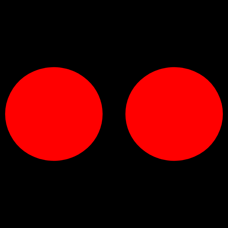
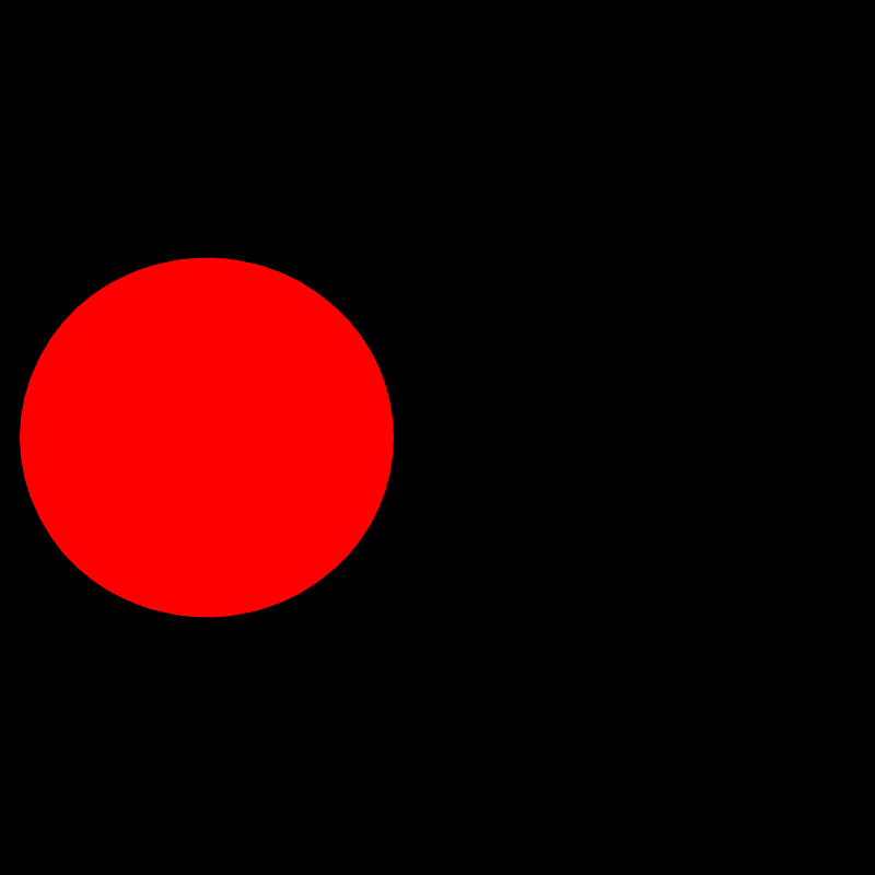
Another unique property of the emissive material property is that the polygon will display at full strength even if there is no light for it to reflect.
          void setup(){
            size(800,800,P3D);
            smooth(8);
            noStroke();
          }
          void draw(){
            background(0);

            ambientLight(0, 0, 0);  // zero strength.

            pushMatrix();
              translate(width * 0.25, height * 0.5, 0);

              ambient(0,0,0);
              emissive(255,0,0);
              sphere(width * 0.2);

            popMatrix();

            pushMatrix();
              translate(width * 0.75, height * 0.5, 0);

              ambient(255,0,0);
              emissive(0,0,0);
              sphere(width * 0.2);

            popMatrix();
          }
So far we have been exploring topics of color and light. Let's move on to position and movement.
Setting up a scene replete with 3D models at various rotations and translations can be a handful. Managing transformation matrices and the position and direction related vector components of lighting effects can become very difficult once more than a few things are present in the scene. Some of the more tedious mathematical hurdles can be conquered by simplifying the scene, and moving the camera within the scene instead.
The camera() function accepts as arguments: the position (x,y,z), where the camera is pointed (x,y,z), and (x,y,z) vector components to describe the 'up direction' of the camera. The default values for the camera are:
          camera(width/2.0, height/2.0, (height/2.0) / tan(PI*30.0 / 180.0),
                  width/2.0, height/2.0, 0,
                  0, 1, 0);
So by default the camera is positioned at the center of the window and some distance away (z-component) from the window that is based on the height. That complicated bit with the (height/2.0) / tan(PI*30.0 / 180.0) is taking into account that a scene that is very wide and tall needs to position the camera far enough away to see the things in the scene. So, in the default state, the z-component of the camera position is bound to the height of the scene.
PVector cameraPosition;
void setup(){
size(512,512,P3D);
smooth(8);
}
void draw(){
background(0);
lights();
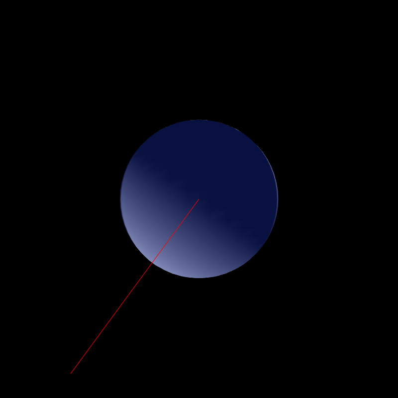
cameraPosition = new PVector(1,-1,1);
cameraPosition.rotate(frameCount * 0.05);
float distance = 300.0;
float eye_x = cameraPosition.x * distance;
float eye_y = -100;
float eye_z = cameraPosition.y * distance;
camera(eye_x, eye_y, eye_z, 0.0, 0.0, 0.0, 0, 1, 0);
box(width * 0.25);
}
Here is what the above scene looks like to a stationary outside observer that can see the camera:
So much can be achieved through simple use of the camera functionality that can't be done easily by changing the position and rotation of the objects in your scene. For example, if you had an object orbiting another object, if you wanted to track that object visually without using the camera you would have to change the position and rotation of all of the objects in your scene relative to that object. You also don't have to place your the objects in your scene relative to the width an height of the window. I don't know about you, but I am sick and tired of typing translate(width * 0.5, height * 0.5, 0); in all of my sketches.
          PVector orbitPosition;

          void setup() {
            size(800, 800, P3D);
            smooth(8);
          }
          void draw() {
            background(0);

            ambientLight(128,128,128);
            directionalLight(128,128,128,1,1,0);

            orbitPosition = new PVector(1, -1, 1);
            orbitPosition.rotate(frameCount * 0.05);

            float distance = 300.0;

            float eye_x = orbitPosition.x * distance;
            float eye_y = 0;
            float eye_z = orbitPosition.y * distance;

            camera(500, -300, 1000, 0, 0, 0, 0, 1, 0);

            if (mousePressed) {
              camera(500, -300, 1000, eye_x, eye_y, eye_z, 0, 1, 0);
            }

            pushMatrix();  // the floor
              translate(0, width * 0.2, 0);
              fill(0, 255, 0);
              stroke(0);
              box(1000, 5, 1000);
            popMatrix();

            pushMatrix(); // the stationary object
              translate(0, 0, 0);
              fill(0, 0, 255);
              noStroke();
              sphere(width * 0.2);
            popMatrix();

            pushMatrix();   // the rotating object
              translate(eye_x, eye_y, eye_z);
              fill(255, 255, 255);
              noStroke();
              sphere(30.0);
            popMatrix();
          }
One line of code yielded results that would otherwise require a complete code reorganization to accomplish.
Your view of your Processing sketch comes through a simulation of a camera lens. The function that allows you to change that view is perspective(). It accepts as its arguments, a field of view, the aspect ratio of the scene, and the position of the near and far clipping planes that, if a polygon were outside of the range, it would not be rendered.
The default values for perspective() are:
          perspective(PI / 3.0,         // 60 degrees, in radians
            width / height,
            camera_z_position / 10.0,
            camera_z_position * 10.0);
Changing the field of view can create a zoom effect without having to reposition the camera. A wide field of view (ex. PI) is the equivalent of being very zoomed out, and a narrow field of view (ex. PI/100.0) simulates being very zoomed in.
        void setup(){
          size(800,800,P3D);
          smooth(8);
          noStroke();
        }
        void draw(){
          background(0);
          lights();

          float fov = map(mouseX, 0, width, PI, PI / 100.0);
          float aspect = (float)width / (float)height;

          perspective(fov, aspect, 10, -1000);

          pushMatrix();
            translate(width * 0.5, height * 0.5, 0.0);
            rotateX(PI * -0.1);
            rotateY(PI * 0.22);
            ambient(33,66,255);
            box(width * 0.25);

          popMatrix();
        }
Let me know if you find any errors! I'm on twitter at @billautomata